

Ever wondered how a single diagram can crack the code of a building’s structure? Wall framing diagrams act like a blueprint that breaks a complex job into clear, easy-to-follow parts. In this guide, we walk through five detailed diagrams that explain the role of soleplates (bottom horizontal boards), header assemblies (support beams above openings), studs (vertical supports), and other key parts.
These maps show exactly how each piece supports the overall frame. They help you plan and build in a smarter, safer, and cost-effective way.
Ready to uncover practical insights that simplify your project? Let’s dive in.
Key Components Illustrated in a Wall Framing Diagram
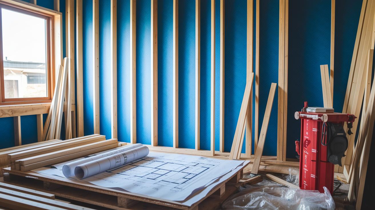
Labels on a wall framing drawing break a complex project into clear, easy-to-follow parts. A well-marked diagram works like a map, guiding you through each step of the framing process and showing exactly where every element goes.
Matching your drawing with trusted guides like wall framing basics (https://neull.com?p=130) lets you check measurements and see how each part fits into the whole structure.
- Soleplate – the bottom board of the wall frame that provides a stable base.
- Top plate(s) – the top board or boards; load-bearing walls often use two top plates for extra strength.
- Studs – vertical boards spaced evenly to hold nails for attaching interior materials.
- Header assembly – a reinforced beam placed over windows or doors. It usually consists of two 2x pieces (actual size about 1.5 in x 3.5 in or 38 mm x 89 mm) with a ½ in (12.7 mm) plywood spacer to support the load above openings.
- Fire blocking – installed in walls taller than 10 ft (3 m) to slow the spread of fire and enhance safety.
- Sheathing/OSB – the external board layer, either plywood or oriented strand board, that covers the frame and adds structural support.
Each of these parts fits together to form a system that bears loads and offers a solid surface for finishing. When every piece is in its proper place, the wall stays straight, secure, and meets building codes for a safe, efficient construction project.
Dimension Specifications on Wall Framing Diagrams
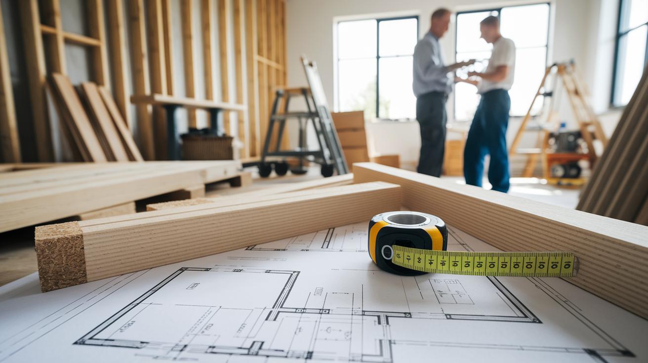
Stud sizes are the basics for wall framing. For load-bearing walls, you typically use 2×4 or 2×6 lumber, and for interior non-load-bearing walls up to 10 ft (3 m) tall, 2×3 studs work well. Start by noting the room's shortest ceiling height and subtract 3 in (76 mm) for the top and sole plates. This step makes sure all your studs are the same length, keeping the wall strong and the blueprint easy to follow.
Spacing depends on the wall’s load. Use 2×4 studs spaced 16 in (40.6 cm) apart for load-bearing walls. Non-load-bearing walls may allow 2×4 studs up to 24 in (61 cm) on-center, but when you choose 2×3 studs, stick to a 16 in (40.6 cm) on-center spacing. These guidelines from the International Residential Code help ensure your walls can support the needed load and guide you clearly when reading diagrams.
Accurate plate marking is key for a uniform layout. Mark the first line on a top or sole plate 15 1/4 in (38.7 cm) from the board’s end. This mark shows where the left edge of the first stud goes. Then, make subsequent marks every 16 in (40.6 cm) along the plate. This approach cuts down on waste and boosts precision at the job site.
Step-by-Step Wall Framing Assembly Diagram Guide

-
Planning and Layout
Start by choosing where your wall will go. If the wall runs perpendicular to the ceiling joists, you have plenty of options. When it runs parallel, line it up with an existing joist or add blocking for extra support. Measure the wall run carefully and mark the top and sole plates. For example, mark the first stud at 15 1/4 in (38.7 cm) from one end, then space each stud 16 in (40.6 cm) apart. -
Cutting Plates and Studs
Measure the shortest ceiling height in the room and subtract 3 in (7.6 cm) to allow for the plates. Cut your top and sole plates to match the wall’s length. Then, cut each stud, including jack studs (support for headers), cripple studs (short studs around openings), and header pieces, to that exact length. This ensures everything fits neatly during assembly. -
Assembling the Frame on the Floor
Lay out all your cut pieces on the floor to form the wall frame. Begin by nailing the sole plate (the bottom horizontal board) to the floor or a block. Next, set each stud along the marked positions on the plate. Assemble the header unit by connecting the jack studs and cripple studs, making sure it lines up correctly to support any openings. -
Raising and Plumping the Wall
Lift the preassembled wall frame into place. Secure the bottom plate tightly against nearby walls or floor blocks. Use a small sledge hammer to tap the top plate so it makes firm contact with the ceiling. Check the wall with a level to ensure it is plumb. -
Installing Double Top Plate and Fire Blocking
Once the wall is in place, add a second top plate to better distribute loads. For walls taller than 10 ft (3 m), include fire blocking (material installed to slow fire spread) to meet safety codes. This final step completes your wall frame as shown in the diagram.
Reference: how to frame a wall step by step (https://neull.com?p=206)
Wall Corner Framing Diagram Techniques
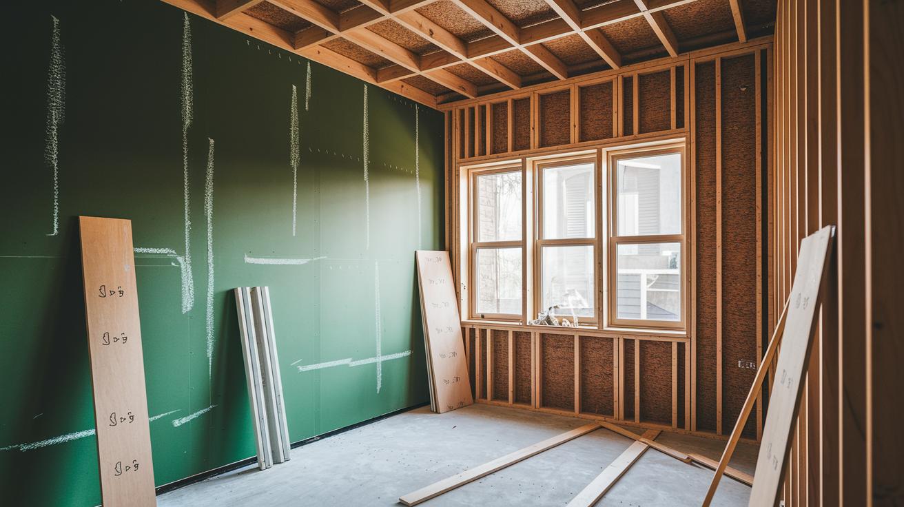
Corner framing is key because these spots bear extra weight and need more nail points to hold drywall and finish materials securely. Diagrams mark these areas clearly, showing exactly where to add extra studs, leave room for insulation, and include fire blocking (a safety measure to slow a fire’s spread). Think of these visuals as a simple map that makes tricky corner details easier to handle.
The three-stud corner method works by using one shared stud between two walls and adding two extra studs to create a full nailing surface. This strong setup makes it easier to hang finishes and leaves plenty of room for insulation and fire blocking. However, it uses more lumber, which can drive up costs and take up a bit more space in tight corners.
The California two-stud corner saves on lumber by using one stud along with a block or a piece of plywood (a sturdy board made from thin wood layers) to form the nail surface for drywall. This method is great when space is tight or when keeping costs low matters most. Though it offers less surface area for nailing, clear diagrams ensure you know where to place everything to support insulation and finishes. Choose this option when simplicity and material efficiency are more important than extra structural build-up.
5 diagram of wall framing: Stunning Structural Insights
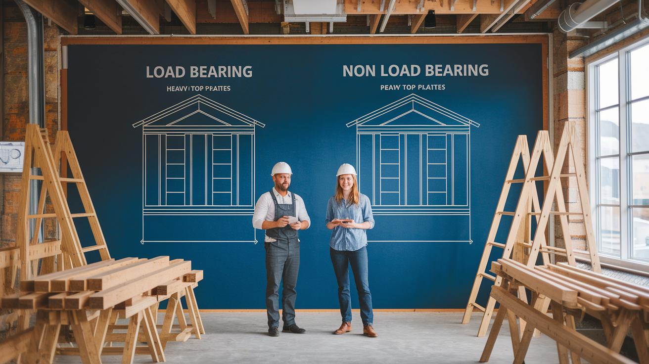
Load-bearing wall diagrams show double top plates and heavy header assemblies. These walls support roof or upper floor loads. They require headers made with two members and a 1/2 in (12.7 mm) plywood spacer to spread the weight over openings. The drawings often include temporary diagonal bracing until the sheathing is on. Clear labels point out these key load-bearing parts so builders know how to transfer the load safely.
Non-load-bearing wall diagrams use a simpler setup. These walls have a single top plate and usually use 2×3 studs for partitions up to 10 ft (3 m) tall. Studs are spaced about 16 inches (406 mm) on center, though some plans use 2×4 studs with wider spacing. Large headers are left out since these openings do not need extra support. This clear layout speeds up construction and helps prevent mistakes.
Additional notes cover bracing details, sheathing tie-ins, and finishing touches. The diagrams show temporary diagonal bracing in load-bearing walls and lighter bracing in non-load-bearing walls to keep the walls square until the final sheathing is applied. These visual cues guide proper drywall installation and clarify each element’s role in overall strength and safety. Clear symbols also help with quality control and finishing the project on time.
Final Words
In the action, you learned how to break down a wall framing project into clear, manageable steps. We reviewed a diagram of wall framing that explains each key component, from the soleplate to the header assembly.
You also discovered how dimensions, cut marks, and different corner techniques shape your layout. We wrapped up with load-bearing vs. non-load-bearing comparisons for practical, safe builds.
Keep these steps in mind, and you'll build projects that are safe, efficient, and budget-friendly.